2012年3月28日水曜日

Intercom and Isadora


I am trying to connect a video intercom to Isadora.

I got a really fancy video intercom which costed like $130 on ebay which came with a SONY CCD.

I figure out that this video intercom uses regular composite video signal.

So I bought Easycap - video capturing hardware and connect intercom's camera to it.
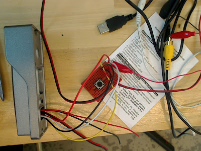


You actually need 12v adopter to supply power to the cam.

Connect the center pin of composite wire to video wire of the cam(in this case white).

Connect black ground wire to composite wire and power supplier.

Connect 12V to red wire of cam.

It is easy.


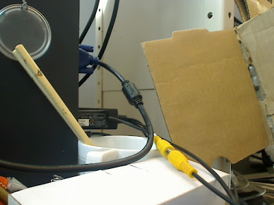
Connect the other side of composite wire to Easycap.


Download the latest version of quick time and Isadora.

You need to go to Pre-Releases of Isadora's webpage and download Isadora v1.3.0f24 for Windows. The regular stable version did not work for my environment.
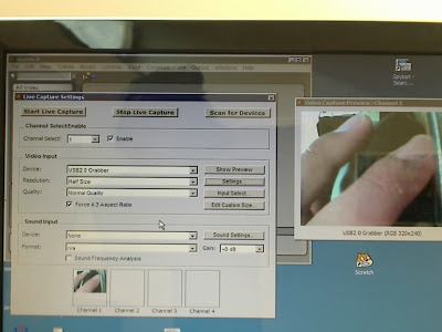


Go to Live capture Setting>Video Input

Device : USB2.0 Grabber.

Resolution : Half Size

Click Settings>NTSC/M

This webpage tells you more detail but it shows slightly different configuration with mine.

At least if you mess around the setup, you can find:-)

http://forum.troikatronix.com/cgi-bin/forum/gforum.cgi?post=13660


***

Additional Info

I realized that latest version of Isadora v1.3.0f24 for Windows does not work well if you run Windows 7 64 bit. I found an older version. It's seems fine. Not so much stable but better than not working..

http://forum.troikatronix.com/forum/TroikaTronix_News_C1/Announcements_F1/Isadora_1.3.0f17_-_Bug_Fixes_(May_20,_2011)_P10598/


2012年3月21日水曜日

eye Tracking device

This is my other work I did.


http://narratibe-project.blogspot.com/

Arduino UNO Assembly

I got an Arduino UNO Assembly from ebay.

To install

Connect Arduino Uno

Open the Device Manager(Windows User) . select the device that is indicated as unknown device(sometime it appears as Arduino Uno but not works properly I guess).

Double click it. in the new window go to Driver tab.

Renew Driver>manually search the driver.

Select the folder which your Arduino software install and chose the driver folder.

A new window may open and may warn you but continue to install.

Wait while. it may take like a minute.


*IMPORTANT

you should have the latest version of the Arduino Software. I had version 0018 it did not work, of course.


However I realized that if you have a GPS shield and not familiar with how to use. It is nice to have Arduino Software Version 0022. The program for GPS provided by sparkfun did not work for the latest version of Arduino Software. I did not check why, yet. I do not have a time now.

This is a great tutorial for arduino GPS shield.

http://www.sparkfun.com/tutorials/173

2012年1月29日日曜日

Reference for XBee

The price of XBee Explorer Dongle is too expensive. $24

If you have a FTDI Basic Breakout($14) you can use it as a replacement. You can save $10.


To connect FTDI and XBee for PuTTY.

Connect

GND-GND

3.3V-VCC

TXO-DIN

TRI-DOUT


In the PuTTY terminal

type +++ without ENTER

XBee will return

OK


2010年11月30日火曜日

For Patrick, check this sample program for your purpose

//sample progrma with shiftresiostors and photosensors
// this program is very basic. you can use one photosensor and upto two shiftresistor so that you can control upto 16 LED with only 3 digital pins of Arduino

//connect photosensor to analog pin 0
int analogData0;


//Pin connected to ST_CP of 74HC595
int latchPin = 8;
//Pin connected to SH_CP of 74HC595
int clockPin = 12;
////Pin connected to DS of 74HC595
int dataPin = 11;

//regure variables
int RadomVal0;


void setup(){
//Start Serial for debuging purposes
Serial.begin(9600);
//set pins to output because they are addressed in the main loop
pinMode(latchPin, OUTPUT);
}

void loop(){
//read data from analog pin 0
analogData0=analogRead(0);
//scale down the value form 0-1023 to 0-255 which works with shift resistor.
analogData0=analogData0/4;
//put a randomize value into variable RadomVal0 this value take form "0" to "the scaled value" so that the new value still reflect the photosensor's value
// this code is optional
RadomVal0 = random(0,analogData0);
// tell shiftresistor to start
digitalWrite(latchPin, 0);
// actual data
shiftOut(dataPin, clockPin,MSBFIRST, RadomVal0);
//if you have second shift resistor. elase // and activate the program
//shiftOut(dataPin, clockPin,MSBFIRST, RadomVal0);
//tell shiftresistor to edn
digitalWrite(latchPin, 1);

// duration of the led light
delay(1000);
}

/*

the following program is optional.
if you want to use the following program replace "void loop" to the following program

void loop(){
//read data from analog pin 0
analogData0=analogRead(0);
//scale down the value form 0-1023 to 0-255 which works with shift resistor.
analogData0=analogData0/4;
// tell shiftresistor to start
//this will enable to light up LED more interestingly
for (int j = 0; j < analogData0; j++) {
digitalWrite(latchPin, 0);
// actual data
shiftOut(dataPin, clockPin,MSBFIRST, RadomVal0);
//if you have second shift resistor. elase // and activate the program
//shiftOut(dataPin, clockPin,MSBFIRST, RadomVal0);
//tell shiftresistor to edn
digitalWrite(latchPin, 1);

// duration of the led light for each led pattern
delay(300);
}
}

*/

2010年11月24日水曜日

high volate control

http://itp.nyu.edu/physcomp/Tutorials/HighCurrentLoads

2010年11月20日土曜日

Arduino Daisy Chain 03


I finally fined a way of daisy chain Arduino.


Prepare two Arduino

Connect USB cable to one of Arduino

Put one side of a wire to 5V of the Arduino that USB is connected to.

The other side of the wire go to vin of the other Arduino.

Connect Tx to Rx of the other Arduino.

Connect Rx to TX of the other Arduino.