2010年6月30日水曜日

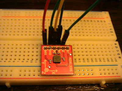
Sensor 08 IR Receiver Breakout


This is a tutorial of How to use IR Receiver Breakout.

Requirement 

IR Receiver Breakout

Arduino

Arduino program

computer

Three wires

Something that can emit IR (Regular remote controller is fine)


Program

/* regular program for a circuit that use analog pin #0

to get a data from sensor.

*/ 


void setup(){

Serial.begin(9600); // Serial connection setup

}

void loop(){

Serial.println(analogRead(0)); //get data and send data

delay(100); // regulate a time

}


2010年6月29日火曜日

One of images for my art work

Three 7 segments advanced controller program

This program is for three 7 segments controlling.

You can display three different digits, such as 4 1 2,7 9 8,0 0 9 and so on.

the program can ignore wrong amount of digits such as 1 2 3 4 5, 2 3, 1 , 0987654 and so on.

the program can ignore wrong combinations of words such as 0 g 0, t k 3 4 4, 1 a 2 s 3 d, and so on.


//reguler variable
int LEDpin = 13;
int c;
int rec1, rec2, rec3;
// error checker
int checkND=0;
//loop counter to change 7 segment
int L=10;
int superL;
int superLL;
int superLLL;
//controller variables
int refleshT=1;
int vTime=500;
int amount7S =3;

void setup()
{
Serial.begin(9600);
for (int i=2; i<10; ++i){
Serial.print("set OUTPUT to digital pin");
Serial.println(i);
pinMode(i,OUTPUT);
}
for (int i=10; i<13; ++i){
Serial.print("set INPUT to digital pin");
Serial.println(i);
pinMode(i,INPUT);
}

pinMode(LEDpin,OUTPUT);
Serial.println("LED is ready to use");
for (int i=10; i<13; ++i){
Serial.print("set pin");
Serial.print(i);
Serial.println("to Ground");
digitalWrite(i,HIGH);
digitalWrite(i,LOW);
}
Serial.println("OK pins are ready");
}
void loop()
{
if(Serial.available()>0){
//reading validity of blocks
block1();
block2();
block3();
//extra protection
EXchecker();
//main protection
if (checkND ==amount7S){
//super high speed loop 60Hz
//main LED loop
for(int FT=0; FT < vTime; ++FT){
L = superL;
c = rec1;
process();
L = superLL;
c = rec2;
process();
L = superLLL;
c = rec3;
process();
}
}
//reset
nothing();
reset();
}//main if end
//protection reset
checkND = 0;
}

//LED controller
void zero(){
nothing();
digitalWrite(2,HIGH);
//digitalWrite(3,HIGH); disabled
digitalWrite(4,HIGH);
digitalWrite(5,HIGH);
//digitalWrite(6,HIGH); disabled
digitalWrite(7,HIGH);
digitalWrite(8,HIGH);
digitalWrite(9,HIGH);
delay(refleshT);
}
void one(){
nothing();
//digitalWrite(2,HIGH); disabled
//digitalWrite(3,HIGH); disabled
//digitalWrite(4,HIGH); disabled
//digitalWrite(5,HIGH); disabled
//digitalWrite(6,HIGH); disabled
digitalWrite(7,HIGH);
digitalWrite(8,HIGH);
//digitalWrite(9,HIGH); disabled
delay(refleshT);
}
void two(){
nothing();
//digitalWrite(2,HIGH); disabled
digitalWrite(3,HIGH);
digitalWrite(4,HIGH);
digitalWrite(5,HIGH);
//digitalWrite(6,HIGH); disabled
//digitalWrite(7,HIGH); disabled
digitalWrite(8,HIGH);
digitalWrite(9,HIGH);
delay(refleshT);
}
void three(){
nothing();
//digitalWrite(2,HIGH); disabled
digitalWrite(3,HIGH);
//digitalWrite(4,HIGH); disabled
digitalWrite(5,HIGH);
//digitalWrite(6,HIGH); disabled
digitalWrite(7,HIGH);
digitalWrite(8,HIGH);
digitalWrite(9,HIGH);
delay(refleshT);
}
void four(){
nothing();
digitalWrite(2,HIGH);
digitalWrite(3,HIGH);
//digitalWrite(4,HIGH); disabled
//digitalWrite(5,HIGH); disabled
//digitalWrite(6,HIGH); disabled
digitalWrite(7,HIGH);
digitalWrite(8,HIGH);
//digitalWrite(9,HIGH); disabled
delay(refleshT);
}
void five(){
nothing();
digitalWrite(2,HIGH);
digitalWrite(3,HIGH);
//digitalWrite(4,HIGH); disabled
digitalWrite(5,HIGH);
//digitalWrite(6,HIGH); disabled
digitalWrite(7,HIGH);
//digitalWrite(8,HIGH); disabled
digitalWrite(9,HIGH);
delay(refleshT);
}
void six(){
nothing();
digitalWrite(2,HIGH);
digitalWrite(3,HIGH);
digitalWrite(4,HIGH);
digitalWrite(5,HIGH);
//digitalWrite(6,HIGH); disabled
digitalWrite(7,HIGH);
//digitalWrite(8,HIGH); disabled
//digitalWrite(9,HIGH); disabled
delay(refleshT);
}
void seven(){
nothing();
digitalWrite(2,HIGH);
//digitalWrite(3,HIGH); disabled
//digitalWrite(4,HIGH); disabled
//digitalWrite(5,HIGH); disabled
//digitalWrite(6,HIGH); disabled
digitalWrite(7,HIGH);
digitalWrite(8,HIGH);
digitalWrite(9,HIGH);
delay(refleshT);
}
void eight(){
nothing();
digitalWrite(2,HIGH);
digitalWrite(3,HIGH);
digitalWrite(4,HIGH);
digitalWrite(5,HIGH);
//digitalWrite(6,HIGH); disabled
digitalWrite(7,HIGH);
digitalWrite(8,HIGH);
digitalWrite(9,HIGH);
delay(refleshT);
}
void nine(){
nothing();
digitalWrite(2,HIGH);
digitalWrite(3,HIGH);
//digitalWrite(4,HIGH); disabled
//digitalWrite(5,HIGH); disabled
//digitalWrite(6,HIGH); disabled
digitalWrite(7,HIGH);
digitalWrite(8,HIGH);
digitalWrite(9,HIGH);
delay(refleshT);
}
void nothing(){
digitalWrite(2,LOW);
digitalWrite(3,LOW);
digitalWrite(4,LOW);
digitalWrite(5,LOW);
digitalWrite(6,LOW);
digitalWrite(7,LOW);
digitalWrite(8,LOW);
digitalWrite(9,LOW);
delay(refleshT);
}

//special loop
//reset pins
void reset(){
for (int e=10; e<13; ++e){
pinMode(e,INPUT);
}
}

//judgement process
void process(){
if(c=='8'){
reset();
pinMode(L,OUTPUT);
eight();
}
else if(c=='0'){
reset();
pinMode(L,OUTPUT);
zero();
}
else if(c=='1'){
reset();
pinMode(L,OUTPUT);
one();
}
else if(c=='2'){
reset();
pinMode(L,OUTPUT);
two();
}
else if(c=='3'){
reset();
pinMode(L,OUTPUT);
three();
}
else if(c=='4'){
reset();
pinMode(L,OUTPUT);
four();
}
else if(c=='5'){
reset();
pinMode(L,OUTPUT);
five();
}
else if(c=='6'){
reset();
pinMode(L,OUTPUT);
six();
}
else if(c=='7'){
reset();
pinMode(L,OUTPUT);
seven();
}
else if(c=='9'){
reset();
pinMode(L,OUTPUT);
nine();
}
else{
nothing();
reset();
return;
}
}

//first block
void block1(){
rec1=Serial.read();
Serial.print("got Serial");//confrmation
Serial.print(rec1,BYTE);
c = rec1;
Cprocess();//check prosecc
superL = 10;
L = superL;
}

//second block
void block2(){
superLL = superL+1;
L = superLL;
rec2=Serial.read();
Serial.print("got Serial");
Serial.print(rec2,BYTE);
c = rec2;
Cprocess();
}

//third block
void block3(){
superLLL = superLL+1;
L = superLLL;
rec3=Serial.read();
Serial.print("got Serial");
Serial.println(rec3,BYTE);
c = rec3;
Cprocess();
}


// EXchecker. protect system from invalid value
void EXchecker(){
if(Serial.available()>0){
int reader = Serial.read();

if(reader == -1){
}
else{
checkND = checkND +10;// protect from hack
}
}
}

// checker
void Cprocess(){
if(c=='8'){
checkND = checkND + 1;
}
else if(c=='0'){
checkND = checkND + 1;
}
else if(c=='1'){
checkND = checkND + 1;
}
else if(c=='2'){
checkND = checkND + 1;
}
else if(c=='3'){
checkND = checkND + 1;
}
else if(c=='4'){
checkND = checkND + 1;
}
else if(c=='5'){
checkND = checkND + 1;
}
else if(c=='6'){
checkND = checkND + 1;
}
else if(c=='7'){
checkND = checkND + 1;
}
else if(c=='9'){
checkND = checkND + 1;
}
else{
nothing();
reset();
return;
}
}


2010年6月28日月曜日

PureData + Arduino


Isadora Arduino


Experiment about 7 segment

Pictures


Movie


Basic three 7-segment control

This is a example of how to show a digit to a 7-segment.

This example display a digit, which is sent from computer on one of three 7-segments.


To do it, you need

Arduino

Arduino program

Computer

Three 7-segments

Eight 220 Ohm resistors

Lot of wires (more than 20)


Circuit


Basically 7-segment is a bunch of LEDs. You need to put a resistor as the same as regular LED.

You have to connect Anode pins of the 7-segments to digital pin number from 2 to 13, no 1 or2 .

You need to connect each 7-segment in parallel. 

In the case of my 7-segment, there is two common cathodes on the 7-segment.

We do not need two, but one of them and connect it to a ground for the case of mine.

If you have a different 7-segment you may have to connect differently. If so, you cannot use program on this tutorial.

However, instead of using a regular ground we will use regular digital pin as a ground.

We will turn several digital pins to ground with a program. It will enable us to control three 7-segments respectively.


Program

you may need to change some cord for your circuit.

I messed up my circuit so that this program is little bit messed up.

//reguler variable
int LEDpin = 13;
int c;
int seg1=10;
int seg2=11;
int seg3=12;

//controller variables
int refleshT=10;

void setup()
{
Serial.begin(9600);
for (int i=2; i<10; ++i){
Serial.print("set OUTPUT to digital pin");
Serial.println(i);
pinMode(i,OUTPUT);
}
for (int i=10; i<13; ++i){
Serial.print("set INPUT to digital pin");
Serial.println(i);
pinMode(i,INPUT);
}

pinMode(LEDpin,OUTPUT);
Serial.println("LED is ready to use");
for (int i=10; i<13; ++i){
Serial.print("set pin");
Serial.print(i);
Serial.println("to Ground");
digitalWrite(i,HIGH);
digitalWrite(i,LOW);
}
Serial.println("OK pins are ready");
}
void loop()
{
if(Serial.available()>0){
c=Serial.read();
Serial.print("get Serial");
Serial.println(c,BYTE);
if(c=='8'){
reset();
pinMode(seg3,OUTPUT);
eight();
}
else if(c=='0'){
reset();
pinMode(seg2,OUTPUT);
zero();
}
else if(c=='1'){
reset();
pinMode(seg1,OUTPUT);
one();
}
else if(c=='2'){
reset();
pinMode(seg1,OUTPUT);
two();
}
else if(c=='3'){
reset();
pinMode(seg3,OUTPUT);
three();
}
else if(c=='4'){
reset();
pinMode(seg2,OUTPUT);
four();
}
else if(c=='5'){
reset();
pinMode(seg1,OUTPUT);
five();
}
else if(c=='6'){
reset();
pinMode(seg2,OUTPUT);
six();
}
else if(c=='7'){
reset();
pinMode(seg2,OUTPUT);
seven();
}
else if(c=='9'){
reset();
pinMode(seg3,OUTPUT);
nine();
}
else{
for (int i=10; i<13; ++i){
Serial.print("reset");
pinMode(i,INPUT);
Serial.print(i);
Serial.println("pin");
}
nothing();
}
}
}

//The following commends are needed to modify for your circuit
void zero(){
nothing();
digitalWrite(2,HIGH);
//digitalWrite(3,HIGH); disabled
digitalWrite(4,HIGH);
digitalWrite(5,HIGH);
//digitalWrite(6,HIGH); disabled
digitalWrite(7,HIGH);
digitalWrite(8,HIGH);
digitalWrite(9,HIGH);
delay(refleshT);
}
void one(){
nothing();
//digitalWrite(2,HIGH); disabled
//digitalWrite(3,HIGH); disabled
//digitalWrite(4,HIGH); disabled
//digitalWrite(5,HIGH); disabled
//digitalWrite(6,HIGH); disabled
digitalWrite(7,HIGH);
digitalWrite(8,HIGH);
//digitalWrite(9,HIGH); disabled
delay(refleshT);
}
void two(){
nothing();
//digitalWrite(2,HIGH); disabled
digitalWrite(3,HIGH);
digitalWrite(4,HIGH);
digitalWrite(5,HIGH);
//digitalWrite(6,HIGH); disabled
//digitalWrite(7,HIGH); disabled
digitalWrite(8,HIGH);
digitalWrite(9,HIGH);
delay(refleshT);
}
void three(){
nothing();
//digitalWrite(2,HIGH); disabled
digitalWrite(3,HIGH);
//digitalWrite(4,HIGH); disabled
digitalWrite(5,HIGH);
//digitalWrite(6,HIGH); disabled
digitalWrite(7,HIGH);
digitalWrite(8,HIGH);
digitalWrite(9,HIGH);
delay(refleshT);
}
void four(){
nothing();
digitalWrite(2,HIGH);
digitalWrite(3,HIGH);
//digitalWrite(4,HIGH); disabled
//digitalWrite(5,HIGH); disabled
//digitalWrite(6,HIGH); disabled
digitalWrite(7,HIGH);
digitalWrite(8,HIGH);
//digitalWrite(9,HIGH); disabled
delay(refleshT);
}
void five(){
nothing();
digitalWrite(2,HIGH);
digitalWrite(3,HIGH);
//digitalWrite(4,HIGH); disabled
digitalWrite(5,HIGH);
//digitalWrite(6,HIGH); disabled
digitalWrite(7,HIGH);
//digitalWrite(8,HIGH); disabled
digitalWrite(9,HIGH);
delay(refleshT);
}
void six(){
nothing();
digitalWrite(2,HIGH);
digitalWrite(3,HIGH);
digitalWrite(4,HIGH);
digitalWrite(5,HIGH);
//digitalWrite(6,HIGH); disabled
digitalWrite(7,HIGH);
//digitalWrite(8,HIGH); disabled
//digitalWrite(9,HIGH); disabled
delay(refleshT);
}
void seven(){
nothing();
digitalWrite(2,HIGH);
//digitalWrite(3,HIGH); disabled
//digitalWrite(4,HIGH); disabled
//digitalWrite(5,HIGH); disabled
//digitalWrite(6,HIGH); disabled
digitalWrite(7,HIGH);
digitalWrite(8,HIGH);
digitalWrite(9,HIGH);
delay(refleshT);
}
void eight(){
nothing();
digitalWrite(2,HIGH);
digitalWrite(3,HIGH);
digitalWrite(4,HIGH);
digitalWrite(5,HIGH);
//digitalWrite(6,HIGH); disabled
digitalWrite(7,HIGH);
digitalWrite(8,HIGH);
digitalWrite(9,HIGH);
delay(refleshT);
}
void nine(){
nothing();
digitalWrite(2,HIGH);
digitalWrite(3,HIGH);
//digitalWrite(4,HIGH); disabled
//digitalWrite(5,HIGH); disabled
//digitalWrite(6,HIGH); disabled
digitalWrite(7,HIGH);
digitalWrite(8,HIGH);
digitalWrite(9,HIGH);
delay(refleshT);
}
void nothing(){
digitalWrite(2,LOW);
digitalWrite(3,LOW);
digitalWrite(4,LOW);
digitalWrite(5,LOW);
digitalWrite(6,LOW);
digitalWrite(7,LOW);
digitalWrite(8,LOW);
digitalWrite(9,LOW);
delay(refleshT);
}

//special loop
//reset pins
void reset(){
for (int e=10; e<13; ++e){
pinMode(e,INPUT);
}
}


Arduino heart beat detection

http://cmpercussion.blogspot.com/2009/07/heartbeat-sensor.html

IC for 7 segment 74HC595

http://www.sparkfun.com/commerce/product_info.php?products_id=733

2010年6月23日水曜日

Testing XBee

I am testing a XBee which is enable Arduino to do a wireless communication.
I build up circuit based on the information of Making Things Talk.

LED blinks.

The circuit works well but the commend on the book did not work some how.

I run PuTTY and did a serial connection

I typed

+++

And got a responce

OK

But the rest of commend did not work.


http://kousaku-kousaku.blogspot.com/2008/10/arduinoxbee-shieldprocessingxbee.html


This webpage is helpful but it is written in Japanese.

I typed

ATID

I got 

3332

Then I typed

ATBD

I got

3

3 means 9600bps

Useful information about commend

http://arduino.cc/en/Main/ArduinoXbeeShield

Serial Communication 


2010年6月22日火曜日

Sensor 07 Gyro (LISY300AL)

Requirements

Wires

Arduino

Gyro (LISY300AL)

Computer with USB

This sensor is easy to program. Just  build a program that read a data from an analog pin.

The pins of sensor seems tricky but basically you connect ST and PD to ground.


Sensor 06 Acceleromenter ADXL335

This is a tutorial for Acceleromenter ADXL335

This exercise will be easy since this we can use analog input for this sensor.

Requirement

Arduino

Acceleromenter ADXL335

wires

Computter and USB


 All the thing that you  have to do is that connect 3.3V to Vcc and connect ground of Arduino and sensor and connect XYZ to analog 0,1,2. Write a program that got a data from analog pins and send them back to computer.

Program

/*

program for Acceleromenter ADXL335

*/

void setup()

{

 Serial.begin(9600);

}

void loop()

{

Serial.print("X");

Serial.print(analogRead(0));

Serial.print("Y");

Serial.print(analogRead(1));

Serial.print("Z");

Serial.println(analogRead(2));

delay(100);

}


Arduino Ethernet Shield with temp sensor

This blog post is badly organized because of the technical difficulty.(Blogger can not show HTML cords )

I highly recommend you to check this blog post with Opera browser.(Even Opera it is disorganized)

http://www.opera.com/

I did not check with other browser such as Safari, FireFox, Chrome and IE.

Do not copy and paste uploaded program to Arduino program. I do not know it is works or not.

Requirement

Temperature/Humidity sensor.

Four wires.

Two Ethernet cable

Router

Arduino

Arduino program

Arduino official Ethernet Shield with WIZnet W5100 chip

USB

computer with Ethernet and USB. 

Knowledge of basic HTML

Finished my former tutorial of Ethernet Shield


In this experiment you will build up webpage that will show a temperature and humidity of the critic room of the sculpture studio. The webpage will broadcast thorugh a Arduino web server.

This experiment based on 

http://wiring.org.co/learning/basics/humiditytemperaturesht15.html

I referred a  program and example of circuit in the webpage.


You will put together Arduino's web server program and temp/humid program.

The program for temperature and humidity sensor is the most difficult program I have ever see.

However, we will modify ready made program so that  it  will not be so much complex.


First we need to do is to open a sample program of the web server.

This program has several functions.


The one is get a data from analog pins.

The second is answer the request of web browser and send a data based on http rule.

The Third is information of webpage itself.


I will not touch anything to the second function so that it will be more easy.

If you look through the program you will see a loop of "for".

In the section you will also see a lot of 

client.print("");

This cord works as the same as "Serial.print".

In stead of send a data through serial connection, client.print send a data through Ethernet.

In side of the parenthesis of the "client.print("");" you will see "

<br />". This is another program called HTML.

Arduino sends a data of HTML to your browser with "client.print".

So if we change contents  of the program of HTML the webpage will show up differently.

 I changed a loop of "for" to the following


client.print("Today's NewPaltz Sculpture Studio");
client.print("<br />");
client.print("temperature");
client.print((long)temperature, DEC);
client.println("<br />");
client.print("humidity ");
client.print((long)humidity, DEC);
client.print("<br />");
client.print("sensor will reload every appx. 2 minute.");
client.print("<br />");
client.print("<image src="http://www.newpaltz.edu/sculpture/images/main_image.jpg">");
client.print("<br />");
client.print("This report send from Critic room by Arduino server and sensor BFA Shotaro.");
client.println("<br />");

the

<img src="" /> is a HTML commend that will show a image. I linked the commend to the picture of the New Paltz sculpture webpage. 

client.print("humidity ");
client.print((long)humidity, DEC);

These are commend that will show data from the sensor.

Do not wrongly erase a commend 

break;

If you do that your web  browser will load a webpage forever.

We already made the program for HTML.


We need to add a program of the sensor.

Basically you can copy the program that you got from the link which I introduced.

And paste them in a certain places.

However there is a one problem will occur.

The program of the sensor contains the commend

delay(300000);

which means that if you copy and paste directly your Arduino server work only every 5 minute.

Since 5 minute is too long, your web browser will be timed out.

Therefor, you need a lack to see the webpage which is none-sense .

However, if we delete it it must be not so good for arduino and server.

In order to avoid this issue we need to modify our program.

if(counter>=100000, ++counter)
{
sendCommandSHT(temperatureCommand, dataPin, clockPin);
waitForResultSHT(dataPin);
val = getData16SHT(dataPin, clockPin);
skipCrcSHT(dataPin, clockPin);
temperature = (float)val * 0.01 - 40;
sendCommandSHT(humidityCommand, dataPin, clockPin);
waitForResultSHT(dataPin);
val = getData16SHT(dataPin, clockPin);
skipCrcSHT(dataPin, clockPin);
humidity = -4.0 + 0.0405 * val + -0.0000028 * val * val;
counter=0;
}
you you change the program to this the Arduino check temperature only every 100 seconds and the rest of the time Arduino works as a server.

Now you are ready.

Setup MAC address and IP address based on former tutorial, upload and connect Ethernet cable.


You can see your webpage from your browser.


2010年6月21日月曜日

Arduino Ethernet shield

I finally figure out to use Ethernet Shield.

Even though Arduino provides a good example of web server, the beginner really does not understand it well.

Also the book "Making Things Talk" did not help me at all. Forget about it, it will not help you so much.


This is a tutorial of how to use Arduino's official Ethernet Shield as a web server. In oder to make a thing simple I do not add any sensor to analog pin of Arduino but you can play around it.  


Requirement

Your computer which has a Ethernet connection and USB. (I will explain about a case of Windows. If you are user of Linux or ... Mac find a same way by yourself. I am not familiar with  Linux and do not have Mac)

Internet connection

Arduino

Arduino program

Official Arduino Ethernet Shield which has a chip WIZnet W5100

two Ethernet cable. Do not use wireless except some situation. Especially if you want to do a same thing at school never use wireless otherwise you will wast 2 hours to realize your problem.

USB cable

Web Browser. (I checked with IE in this time, but I think I really does not matter)

A little knowledge of network(I will explain later).


Step one

First thing you need to do is to build Arduino Ethernet shield ready to use.

see the following picture.


you can add sensor to the analog pin if you want you will those value through the Internet.

+ Do not connect any thing to the digital pins number 10, 11, 12, and  13 . Even though they are looked vacant pins since they are already used by Ethernet Shield.

Second Step

Load a ready made program that is in samples.

File>Examples>Ethernet>WebServer.


The ready made program will be load in a new window.

However it is not ready to upload them.

If you see the program you will see a cords


byte mac[] = { 0x00, 0x00, 0x00, 0x00, 0x00, 0x00 };
byte ip[] = { 127, 0, 0, 1 };

Server server(80);

These are very fundamental information of network.

Since I am not a specialist of network, I can not tell exactly but mac and ip are addresses that indicate your computer. 

the number 80 is called a port number. Usually "http"(which you often seen in a address bar of the browser) uses port number 80.

Before upload we have to figure out and tell the address of the Arduino. (I think probably that is because Arduino Ethernet shield do not have a function of DHCP server.)

Step 3

Detect addresses.

Fortunately, we do not need to spend so much effort to figure out addresses.

In the book "Making Things Talk" mention about the software PuTTy(PuTTy is Only for Windows, Linux and Mac need other software) in order to find a address called MAC address.

MAC address is a physical address that is recorded in your microchip and it will not change.(We also need IP address that will change normally unless you have a fixed IP address or do a special setup.

Look at a back side of Arduino Ethernet Shield 

You will see unfamiliar numbers that is looked like XX-XX-XX-XX-XX-XX

Since it is a hexadecimal number system the numbers contain alphabet. 


These numbers(Actually number) are called MAC address.  

Next you need to find your IP address.

Connect your computer to the Internet with Ethernet Cable.

You need to do a "Hacker" like thing to find. 

======Windows only ========================

go to Start> accessory>command prompt.

You will see DOS  window(I do not know how many people know DOS but)

You have to use it CUI

Type following and hit Enter:

ipconfig /all

This is a very useful commend that worth to remember.

You will see following thing


(sorry my computer runs Japanese operating system)

You will probably see "IPv4 address" which is your IP address.

IP address is looked like thins:

127.0.0.1

Now you have all the information you need.

=============For Linux and Mac and Windows user, who do not like CUI,===========

Go a web page that will tell your IP address. There are so many web page that tells your IP address.

Do not use proxy server and also your Internet security application potentially cause problem.

Linux must have a command that tells your IP address, since it is a operating system mainly for server but I am not sure.

I think Mac also has similar thing but I do not know.

==================================================================


go back to the program and replace the number to your number.

byte mac[] = { 0x00, 0x00, 0x00, 0x00, 0x00, 0x00 };
byte ip[] = { 127, 0, 0, 1 };

Server server(80);

 You do not need to do any thing for port number unless your router has some special setup.

Step 4

You are ready to upload a program to the Arduino.

Upload the program.

Unplug the Ethernet cable that is connected to your computer(only the side of computer) and plug it to Arduino.


Bring another new cable and connect  your computer and the router.

Step 5

Run a browser.

I use IE since I used a school computer that was already connected to the network.

In the browser's address bar, type the IP address that you program.


http://127.0.0.1(use your own number.)


The number something like 127.0.0.1 is same as http://www.google.com they are looked different but they actually almost same. Since for humans  IP address is not easy to remember, a DNS server change it to words that human can easily remember.

(127.0.0.1 does not indicate Google webpage. 127.0.0.1 is a special IP address that is indicate your computer(localhost) so that if you run server system in your computer with Apache you will use it.)  


If you see a information of analog pin of Arduino.

If you choose other than 80 for port number you need to specify the port.


http://127.0.0.1:8080

I you have any trouble it must be caused by firewall of the router, programed wrong number or other many reasons. 


2010年6月20日日曜日

Controlling relay to Arduino

This practice is very useful for you.

Since it is allow you to control other electrical devices that use regular 120V power.

Be safe when you do this experiment. Never touch 120V exposed cables and relay.

Requirement

Arduino

Relay(I was already setup a relay to ready to use this experiment)

Power supply

Wires

Switch

Resistor


Circuit

The relay, which I used for this experiment, has a  three pins for Arduino.

one is for 5V. one is for ground. and rest of it is for controlling which you need to connect to digial pin.

Program

 Basically, you will build up program that send a 1 or 0 to the pin that you connect the relay.

You will got  data of 0 and 1 sent from the switch.


WorkPictures


Practing with a book "Making Things Talk"


I am researching serial communication.

 Note: if you plan to do a practice page 41, you should be careful.

I highly recommend you to add a following cord to the void loop section of  the sample cord.

delay(10);

Otherwise Arduino program will scream. (if you have a single core CUP, your operating system will also scream) 

My laptop, which has a CPU Intel Core2DUO 2.4Gh, is not a  slow computer but one of CUP core was occupied by the Arduino program and the Arduino program responded very very slowly.


2010年6月19日土曜日

2010年6月17日木曜日

Part of idea sketches

Rendered by Mental Ray Maya 2010. Edited by Photoshop CS4


Part of my idea sketch

I worked with Autodesk Maya 2010

2010年6月15日火曜日

Make a simple work with Lily Pad Arduino


LilyPad Arduino is a wearable Arduino.

It uses conduct threads in stead of regular metal wires so that it enable to make a wearable art work or interactive wall cloth.

I did a following experiment with Lily pad; however, I do not recommend you to do a same thing with me since I did not planed perfectly and it was the first time trial. 

I made a gloves with LED. If I press or hold something with finger, the color of LED will be changed. 

Requirement

Lily pad Arduino

conduct thread

power supply for Lily pad Arduino

AAA battery  

10K resistor

Force sensor

LED that came with Lily Pad

Sewing Stuffs (needle, thread)

Cloth or material which you want to be sewed 


Warning: this experiment potentially causes unexpected danger to you and Arduino.

Be safe when you do a experiment with Lily Pad.

If you find anything that unexpected result, plug out power charger( USB or battery ).

I actually almost broke down the circuit of the LilyPad because of shorts of the circuit.

First thing that you need to do is to imagine the final form of the circuit.

It must be better to spend a time to figure out how you sew thread to the glove.

I am sure that you will encounter a lot of problems while you are sewing since I also encountered a lot of problems.

Basic idea of circuit


As you see some of the threads nearly touch each other, that really bad.

I should have planned more nicely.


Program


int ledPin=10; // declare variables
int ledPin2=10;
int pressure=0;
int val,val2;
void setup()
{
  pinMode(ledPin, OUTPUT); //setup pin
}
void loop()
{
  val = analogRead(pressure)/4;

//load data and convert it to suitable value for PWM
val2 = 255-val;

//load data and convert it to suitable value for PWM
analogWrite(ledPin, val);
delay(400);
analogWrite(ledPin, val2);
delay(400);
}


Maya + Arduino (python)

http://jp.makezine.com/blog/2008/12/maya_and_arduino_control.html?CMP=OTC-T10K41815721

http://danthompsonsblog.blogspot.com/2008/08/maya-python-arduino-servo.html

Arduino shield

http://koress.jp/2010/05/arduinoap_shield.html

2010年6月12日土曜日

Sensor 05 Forece sensor

Building up force sensor

Requirements

Arduino

10K Ohm Resistor

Force sensor

Wires


Circuit


Program

The program for force sensor is simple

int pinX=0; //variables

int dataX;

void setup()
{
Serial.begin(9600); //setup serial speed
}
void loop()
{
dataX=analogRead(pinX); // read a value

Serial.println(dataX);//send a value to PC


delay(100);//regulate a time
}


 or you can use more shorter program


void setup()
{
Serial.begin(9600); //setup serial speed
}
void loop()
{

Serial.println(analogRead(0));//read and send a value to PC


delay(100);//regulate a time
}


whichever you want

Experiment Movie