http://www.lulu.com/items/volume_63/1108000/1108699/4/print/ARDUINO_NOTEBOOKv6.pdf
This tutorial is based on the PDF page 35 about servo, and I changed program to check my understanding of the tutorial.
The PDF tutorial has a good information but the program seems complex. I simplified a program and add a little function.
In the following tutorial I am going to explain the way to control servo motor in a different way that explained in a tutorial of the Arduino web page.
In way that is introduced in a Arduino web page is use servo library to control the servo motor. Therefore, only pin9 and pin10 is available for servo.
However, the pin 9 and 10 has a function of pwm and you might want to use them for other purposes.
This tutorial enable you to use any digital pin to control servo motor.
Requirements
Servo motor
(you may need a pin that has three legs both side to connect servo to the board)
10K resistor
Switch
Wires
Arduino

Before we start we need to understand more about servo motor
From the PDF
http://www.lulu.com/items/volume_63/1108000/1108699/4/print/ARDUINO_NOTEBOOKv6.pdf
"Hobby servos are a type of self-contained motor that can move in a 180º arc. All that is needed is a pulse sent every 20ms."
From the Arduino web page
http://arduino.cc/en/Tutorial/Knob
"Servo motors have three wires: power, ground, and signal. The power wire is typically red, and should be connected to the 5V pin on the Arduino board. The ground wire is typically black or brown and should be connected to a ground pin on the Arduino board. The signal pin is typically yellow or orange and should be connected to pin 9 on the Arduino board."
I found additional useful information from Wikipedia
http://en.wikipedia.org/wiki/Servo_motor
"A servo pulse of 1.5 ms width will set the servo to its "neutral" position, or 90°. For example a servo pulse of 1.25 ms could set the servo to 0° and a pulse of 1.75 ms could set the servo to 180°. The physical limits and timings of the servo hardware varies between brands and models, but a general servo's angular motion will travel somewhere in the range of 180° - 210° and the neutral position is almost always at 1.5 ms."
Now we got a enough information to program and build up circuit, so that let's try based on these information.
Circuit
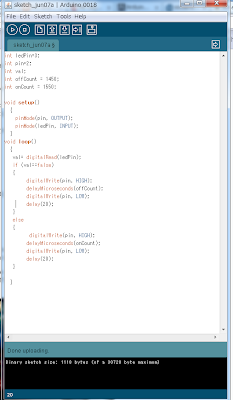
Program
/*
This program is enable you to rotate a servo motor without using a Arduino library.
If you hit a switch the motor will rotate opposite direction.
*/
int ledPin=3;//switch
int pin=2;//for servo motor control
int val;
int offCount = 1450;// you can change the rotation of the servo motor
int onCount = 1550;//same as here
void setup()
{
pinMode(pin, OUTPUT);//set up pins
pinMode(ledPin, INPUT);
}
void loop()
{
val= digitalRead(ledPin); // get data from switch
if (val==false)
//check whether switch is on or off you can use 0 instead of false
{
digitalWrite(pin, HIGH); //send a pulse
delayMicroseconds(offCount);//it is important for servo motor
digitalWrite(pin, LOW);
delay(20);// also important. If you omit it, the motor do not work properly.
}
else
{
// when you switch on
digitalWrite(pin, HIGH);
delayMicroseconds(onCount);
digitalWrite(pin, LOW);
delay(20);
}
}
If you put a value 1500 at offCount or onCount ot both the motor does not work but it does not mean broken but it is balanced.
I do not know how much angle does our servo motor can take, but we can put a value from 1250 to 1750 safely.
Extra
Ardui-Bot (Arduino on the Boe-Bot frame)


0 件のコメント:
コメントを投稿